sales4@yodeldrag.com
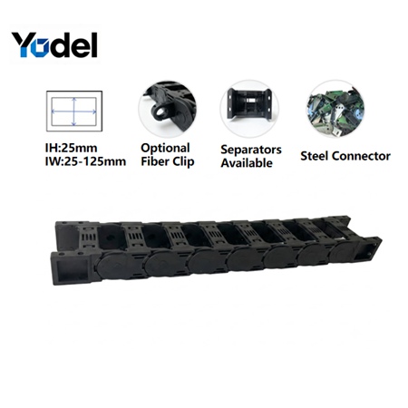
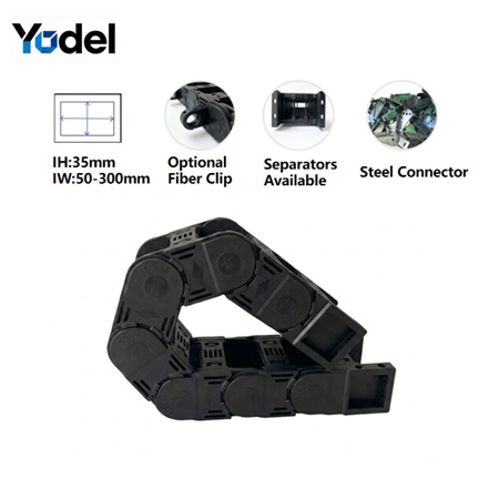
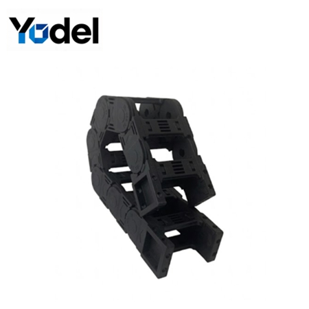
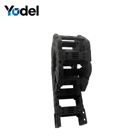
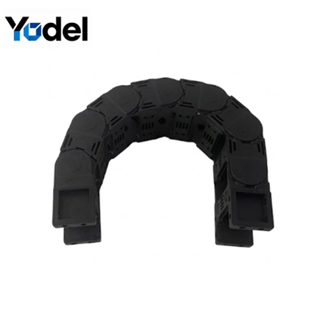
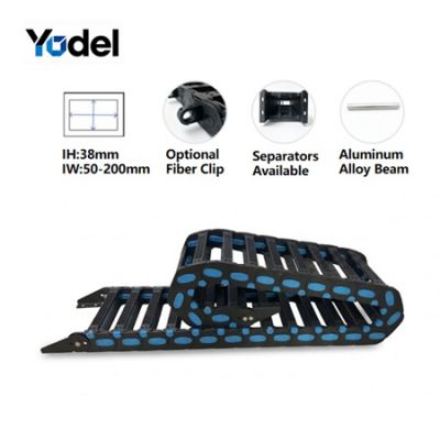
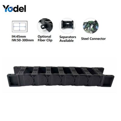
1. Inner Height:25 mm 35mm
2. Material:PA66 Nylon + ≥30% Glass Fiber
3. Style:Bridge (open)
4. Optional Add-ons:Built-in separators, steel joints, fiber optic clip
5. Temperature Range:-40°C to +120°C
6. Key Strengths:High load, anti-deformation, wear-resistant
7. Suitable Motion:High-frequency reciprocating
8. Suitable industries:Mining Machinery | Construction Equipment | Port & Marine Handling | CNC Machine Tools | Automated Assembly Lines | Material Handling Systems | Conveyors & Hoists | Industrial Gantries | Heavy-Duty Robotics | Ship Loaders & Unloaders | Drilling Rigs | Container Cranes | Metal processing | Stone quarrying | Outdoor heavy machinery | Automated welding | Foundry | Forging | Heavy gantry systems
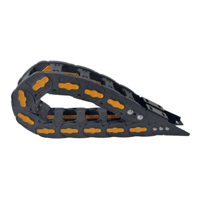
In high-speed automation and precise CNC machinery manufacturing, managing moving cables and pneumatic hoses securely is a core engineering challenge. Standard nylon tracks often warp, sag, or fail prematurely under rapid acceleration. Our premium 25mm and 35mm inner height plastic cable drag chain series introduces structural advancements engineered explicitly for robust cable protection and extended duty cycles.
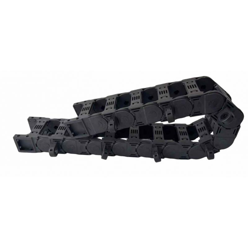
Unlike generic extrusion parts, this heavy-duty bridge type cable chain structure relies on an optimized open-frame design. This configuration maximizes heat dissipation and grants visual access for instant cable inspection, significantly dropping machine downtime. Built from professional-grade Nylon PA66 integrated with over 30% advanced glass fiber reinforcement, this specialized nylon drag chain preserves excellent tensile strength, rigidity, and dimensional stability, even when operating under sustained dynamic loads and continuous high-velocity travel profiles.
Advanced PA66 + GF30 Matrix: Infused with more than 30% structural glass fiber, this plastic cable drag chain prevents thermal expansion and structural bowing during continuous long-term friction.
Modular Vertical Separation: Engineered exclusively with customizable vertical separators to prevent internal cable overlapping and alignment drift. Note: This series supports vertical dividers only, ensuring clean linear alignment without complex multi-tiered grid friction.
Integrated Fiber Optic Clips: Dedicated clip modules safeguard sensitive, low-bend-radius data lines and fiber optics from being crushed by heavier power cables.
Hybrid Bracket System: Choose between lightweight, wear-resistant nylon end connectors or ultra-robust steel mounting brackets to interface seamlessly with your heavy machinery chassis.
A multi-axis precision CNC engraving router required a flexible cable track chain to guide motor power lines and unshielded signal lines alongside a 12mm pneumatic vacuum tube. Due to high acceleration across the X-axis, ordinary plastic carriers frequently warped, introducing signal interference.
By deploying our 25mm inner height plastic cable drag chain fitted with dedicated vertical separators, the signal lines and pneumatic tubes were entirely isolated. The >30% glass fiber matrix eliminated structural sag across a 2.5-meter free-carrying stroke, operating flawlessly at velocities exceeding 3.5 m/s.
An automated optical inspection line required continuous routing of sensitive high-speed fiber-optic lines and heavy multi-core power lines. Because standard nylon tracks can crush delicate data conduits during sudden stops, our 35mm cnc cable drag chain equipped with integrated optical fiber clips was integrated.
The optical links were nested within tension-free clips, while heavy power lines rested on the lower deck, separated by vertical partitions. The hybrid steel end connectors locked the assembly to the machine chassis, handling over 8 million cycles without track fatigue.
Selecting the exact sizing parameters for your nylon drag chain directly affects the lifespan of internal cables. Follow this systematic industrial sizing protocol to calculate the necessary spacing criteria:
When packing conduits inside the plastic cable drag chain, you must maintain a mandatory clearance buffer. Let Dmax represent the outer diameter of the single thickest cable in the bundle, and di denote individual cable diameters.
For horizontal layout sizing, ensure the combined cross-sectional clearance complies with the following layout rule:
Engineering Example: If you are routing two 12mm power cables and one 8mm pneumatic hose, the absolute minimum internal width must accommodate the physical spacing plus a minimum 10% movement clearance for each element, preventing internal friction build-up.
The bending radius should always be determined by referring to the thickest or least flexible cable in your assembly. For standard flexible dynamic cables, use the following formula:
For sensitive optical cables or rigid pneumatic lines, increase this parameter to avoid attenuation or kinking:
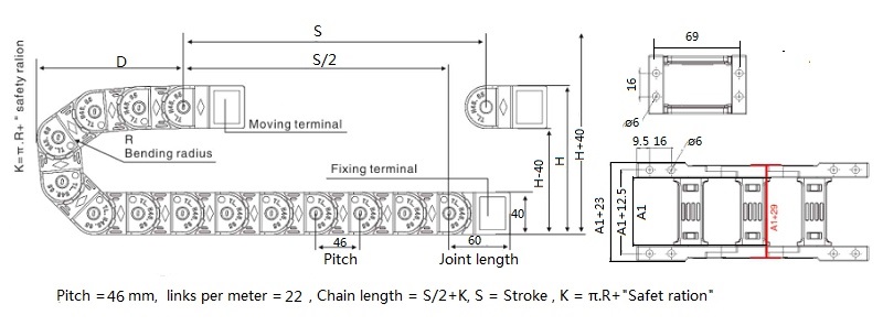
| Model | Inner Height mm | Inner Width mm | Outer Height mm | Outer Width mm | Bending Radius mm |
| HD25.25 | 25 | 25 | 40 | 44 | 55 75 100 125 150 175 200 |
| HD25.38 | 25 | 38 | 40 | 57 | |
| HD25.50 | 25 | 50 | 40 | 69 | |
| HD25.57 | 25 | 57 | 40 | 76 | |
| HD25.60 | 25 | 60 | 40 | 79 | |
| HD25.70 | 25 | 70 | 40 | 90 | |
| HD25.75 | 25 | 75 | 40 | 94 | |
| HD25.77 | 25 | 77 | 40 | 96 | |
| HD25.103 | 25 | 103 | 40 | 122 | |
| HD25.125 | 25 | 125 | 40 | 144 |
| Model | Inner Height mm | Inner Width mm | Outer Height mm | Outer Width mm | Bending Radius mm |
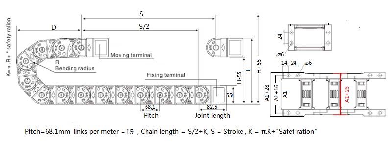
| HD35.50 | 35 | 50 | 55 | 75 | 75 100 125 150 175 200 250 300 |
| HD35.60 | 35 | 60 | 55 | 85 | |
| HD35.75 | 35 | 75 | 55 | 100 | |
| HD35.90 | 35 | 90 | 55 | 115 | |
| HD35.100 | 35 | 100 | 55 | 125 | |
| HD35.117 | 35 | 117 | 55 | 142 | |
| HD35.125 | 35 | 125 | 55 | 150 | |
| HD35.150 | 35 | 150 | 55 | 175 | |
| HD35.175 | 35 | 175 | 55 | 200 | |
| HD35.200 | 35 | 200 | 55 | 225 | |
| HD35.250 | 35 | 250 | 55 | 275 | |
| HD35.300 | 35 | 300 | 55 | 325 |
Yodel Technology Development Co., Ltd. is a professional cable carrier manufacturer in China with 15+ years of industry expertise, dedicated to providing various types, high-quality and cost-effective fastening solutions to global customers.[read more]


Contact Person : Tinny Tan
Te l : 8619922601285
E-mail : sales4@yodeldrag.com
Add : Chengnan Development Zone, Yanshan County, Hebei Province