sales4@yodeldrag.com
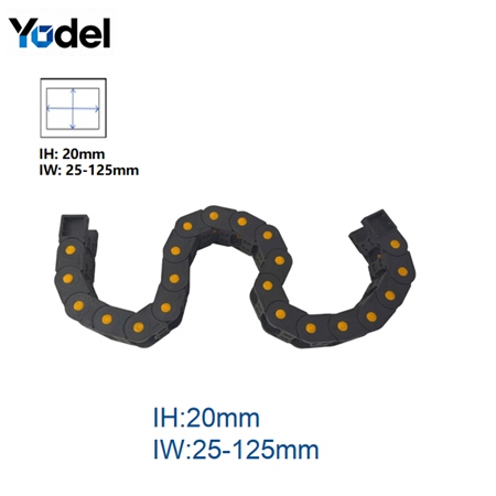
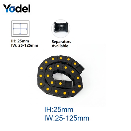
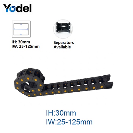
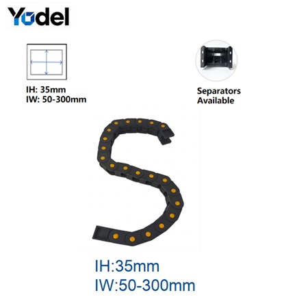
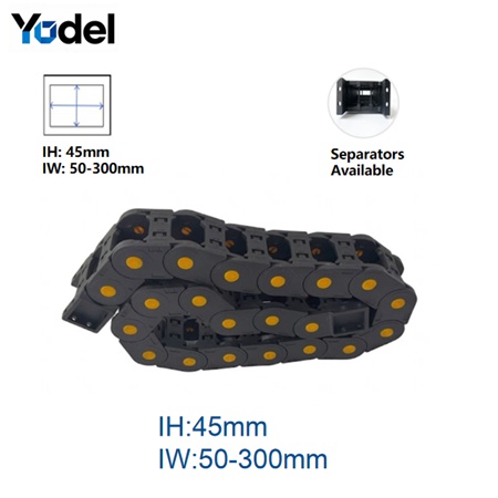
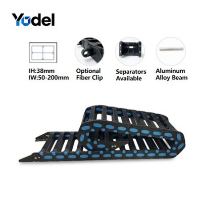
1. Material : PA66 nylon with glass fiber
2. Inner Height :20mm/25mm/30mm/35mm/45mm
3. Bending Direction: Bidirectional (forward and reverse)
4. Structure: Bridge type
5. Wide temperature resistance: -40℃ ~ +120℃
6. Suitable industries: CNC & Metalworking | Industrial Automation & Robotics | Packaging & Wood Processing | Automated Logistics
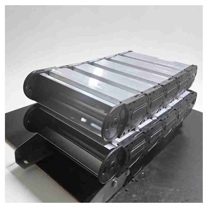
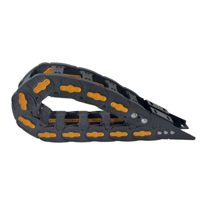
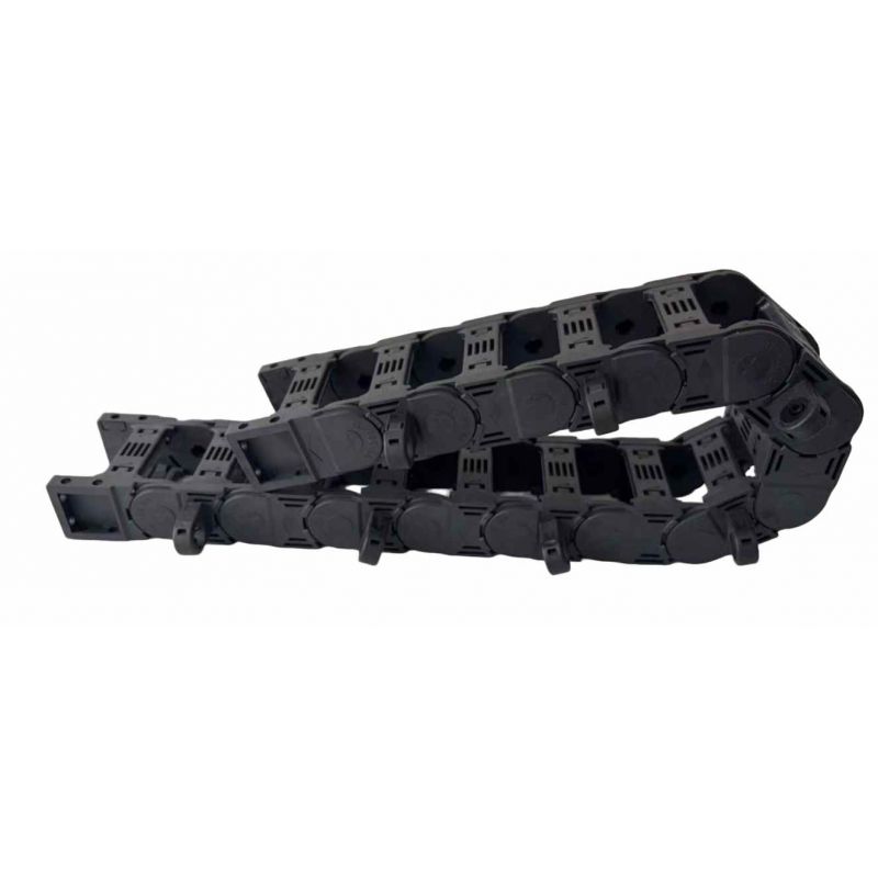
When standard, single-radius cable tracks fail under multi-axis tortional loads, the S-Shaped Nylon Drag Chain offers unmatched reliability. Engineered specifically for complex reverse-bending geometries, this premium bridge-type flexible cable chain provides seamless 3D routing for high-speed automated systems.
By utilizing modified Nylon PA66 structurally fortified with high-density glass fiber, this plastic energy chain cable carrier withstands structural deflection, high acceleration velocities, and severe mechanical stress. Featuring an open bridge-type cross-section, it allows for maximum thermal dissipation, continuous visual inspection, and instant cable drop-in configurations. Whether tracking complex optical fiber links or acting as a rugged wire carrier drag chain for hydraulic hoses, this system guarantees zero-snag motion.
Traditional cable tracks only yield to a single bending radius (R). This engineering limitation causes whipping, binding, and catastrophic structural fatigue when automated machinery requires an alternative or reverse-curve dynamic footprint.
[Standard Motion] ====> Single Bending Radius (R) Only [S-Type Kinematics] ====> (+R) Forward Bend + (-R) Reverse Bend Simultaneously
True Reverse-Bend Radius Consistency: Enables dual-axis bending (+R and -R) within a single continuous run.
Glass-Fiber Matrix Armor: Infused with specialized fiberglass elements to elevate tensile strength while ensuring structural integrity under high-velocity inertial changes.
Self-Lubricating Pin Joint Architecture: Lowers friction thresholds at the link connection points, preventing material shedding and ensuring cleanroom-compatible operation.
Deep Dive — Real-World Application Case Study
A leading automotive components manufacturer faced recurring machine downtime due to premature shielding failures on their custom 5-axis CNC router arms. Standard drag chains suffered torsional twisting, compressing internal lines during high-G reverse directional shifts.
The engineering team integrated our CNC Cable Track Chain running an S-curve layout.
The Result: The specialized bi-directional cable chain drag links cleanly absorbed the rapid directional changes of the gantry. The open-bridge configuration prevented heat retention in the heavy-duty lines, extending the lifespan of both the internal pneumatic control lines and high-flex servo cables by over 400%.
To secure peak service life from your flexible cable chain, follow this rigorous structural sizing protocol before selecting your inner width (Bi) and inner height (Hi)
Gather all outer diameters (d) of your cable array. The internal cavity of your plastic energy chain cable carrier must maintain a mandatory clearance threshold:
For Electrical/Data Cables: Leave a minimum clearance gap of at least 10% around the thickest cable.
For Hydraulic/Pneumatic Hoses: Leave a minimum clearance gap of at least 20% to accommodate dynamic pressure dilation.
Advanced Bi-Directional Cable Chain Drag Kinematics: Effortlessly handles back-bending routing schemes without increasing mechanical friction or joint resistance.
Optimized CNC Cable Track Chain Interface: Seamlessly mounts to high-acceleration CNC gantries, reducing system resonance and tracking vibrations.
Heavy-Duty Utility: Functions smoothly as a high-tensile wire carrier drag chain for hydraulic hoses and multi-conductor power lines.
Modular Link Interlocking: Allows links to be added or removed in seconds, making adjustments simple without requiring specialized breakdown tools.
A: Unreinforced polymers bow and twist under heavy payloads or long travel extensions. Infusing glass fiber significantly increases tensile modulus and structural rigidity, allowing the chain to support heavy cable loads over long distances without sagging or jamming during fast directional shifts.
A: Absolutely. The heavy-duty bridge construction is designed to distribute weight evenly. When used as a wire carrier drag chain for hydraulic hoses, we highly recommend installing vertical interior separators to isolate high-pressure hoses from sensitive data lines.
A: S-curve travel configurations require calculating the sum of both individual travel loops plus the central neutral transition zone. Reach out directly to our global engineering team with your machine layout file for a customized calculation.
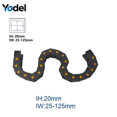
Inner height 20mm series :
| Model | Inner Height (mm) | Inner Width (mm) | Outer Height (mm) | Outer Width (mm) | Bending Radius (mm) |
| S20BK.01 | 20 |
25 |
35 |
43 |
55 |
| S20BK.02 | 20 |
38 |
35 |
56 | |
| S20BK.03 | 20 |
50 | 35 |
68 | |
| S20BK.04 | 20 |
57 | 35 |
75 | |
| S20BK.05 | 20 | 60 | 35 | 78 | |
| S20BK.06 | 20 | 70 | 35 | 89 | |
| S20BK.07 | 20 | 75 | 35 | 93 | |
| S20BK.08 | 20 | 77 | 35 | 95 | |
| S20BK.09 | 20 | 100 | 35 | 108 | |
| S20BK.10 | 20 | 103 | 35 | 121 | |
| S20BK.11 | 20 | 125 | 35 | 143 |
Inner height 25mm series :
| Model | Inner Height (mm) | Inner Width (mm) | Outer Height (mm) | Outer Width (mm) | Bending Radius (mm) |
| S25BK.01 | 25 |
25 |
40 | 44 |
55 |
| S25BK.02 | 25 |
38 |
40 | 57 | |
| S25BK.03 | 25 |
50 | 40 | 69 | |
| S25BK.04 | 25 |
57 | 40 | 76 | |
| S25BK.05 | 25 | 60 | 40 | 79 | |
| S25BK.06 | 25 | 70 | 40 | 90 | |
| S25BK.07 | 25 | 75 | 40 | 94 | |
| S25BK.08 | 25 | 77 | 40 | 96 | |
| S25BK.09 | 25 | 100 | 40 | 109 | |
| S25BK.10 | 25 | 103 | 40 | 122 | |
| S25BK.11 | 25 | 125 | 40 | 144 |
Inner height 30mm series :
| Model | Inner Height (mm) | Inner Width (mm) | Outer Height (mm) | Outer Width (mm) | Bending Radius (mm) |
| S30BK.01 | 30 |
25 |
45 | 45 |
55 |
| S30BK.02 | 30 |
38 |
45 | 58 | |
| S30BK.03 | 30 |
50 | 45 | 70 | |
| S30BK.04 | 30 |
57 | 45 | 77 |
|
| S30BK.05 | 30 |
60 | 45 | 80 | |
| S30BK.06 | 30 | 70 | 45 | 91 | |
| S30BK.07 | 30 | 75 | 45 | 95 | |
| S30BK.08 | 30 | 77 | 45 | 97 | |
| S30BK.09 | 30 | 100 | 45 | 110 | |
| S30BK.10 | 30 | 103 | 45 | 123 | |
| S30BK.11 | 30 | 125 | 45 | 145 |
Inner height 35mm series :
| Model | Inner Height (mm) | Inner Width (mm) | Outer Height (mm) | Outer Width (mm) | Bending Radius (mm) |
| S35BK.01 | 35 |
50 |
55 |
75 |
75 |
| S35BK.02 | 35 |
60 |
55 |
85 |
|
| S35BK.03 | 35 |
75 | 55 |
100 | |
| S35BK.04 | 35 |
90 | 55 |
115 |
|
| S35BK.05 | 35 |
100 | 55 |
125 | |
| S35BK.06 | 35 | 117 | 55 | 142 |
|
| S35BK.07 | 35 | 125 | 55 | 150 |
|
| S35BK.08 | 35 | 130 | 55 | 155 |
|
| S35BK.09 | 35 | 150 | 55 | 175 | |
| S35BK.10 | 35 | 175 | 55 | 200 |
|
| S35BK.11 | 35 | 200 | 55 | 225 |
|
| S35BK.12 | 35 | 250 | 55 | 275 | |
| S35BK.13 | 35 | 300 | 55 | 325 |
Inner height 45mm series :
| Model | Inner Height (mm) | Inner Width (mm) | Outer Height (mm) | Outer Width (mm) | Bending Radius (mm) |
| S45BK.01 | 45 |
50 |
65 |
77 |
75 |
| S45BK.02 | 45 |
60 |
65 |
87 |
|
| S45BK.03 | 45 |
75 | 65 |
102 | |
| S45BK.04 | 45 |
90 | 65 |
117 |
|
| S45BK.05 | 45 |
100 | 65 |
127 | |
| S45BK.06 | 45 | 117 | 65 | 145 |
|
| S45BK.07 | 45 | 125 | 65 | 152 |
|
| S45BK.08 | 45 | 130 | 65 | 157 |
|
| S45BK.09 | 45 | 150 | 65 |
177 | |
| S45BK.10 | 45 | 175 | 65 | 202 |
|
| S45BK.11 | 45 | 200 | 65 | 227 |
|
| S45BK.12 | 45 | 250 | 65 | 277 | |
| S45BK.13 | 45 | 300 | 65 | 327 |
Yodel Technology Development Co., Ltd. is a professional cable carrier manufacturer in China with 15+ years of industry expertise, dedicated to providing various types, high-quality and cost-effective fastening solutions to global customers.[read more]


Contact Person : Tinny Tan
Te l : 8619922601285
E-mail : sales4@yodeldrag.com
Add : Chengnan Development Zone, Yanshan County, Hebei Province