sales4@yodeldrag.com
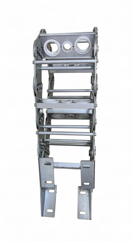
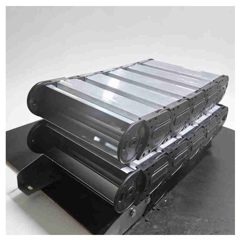
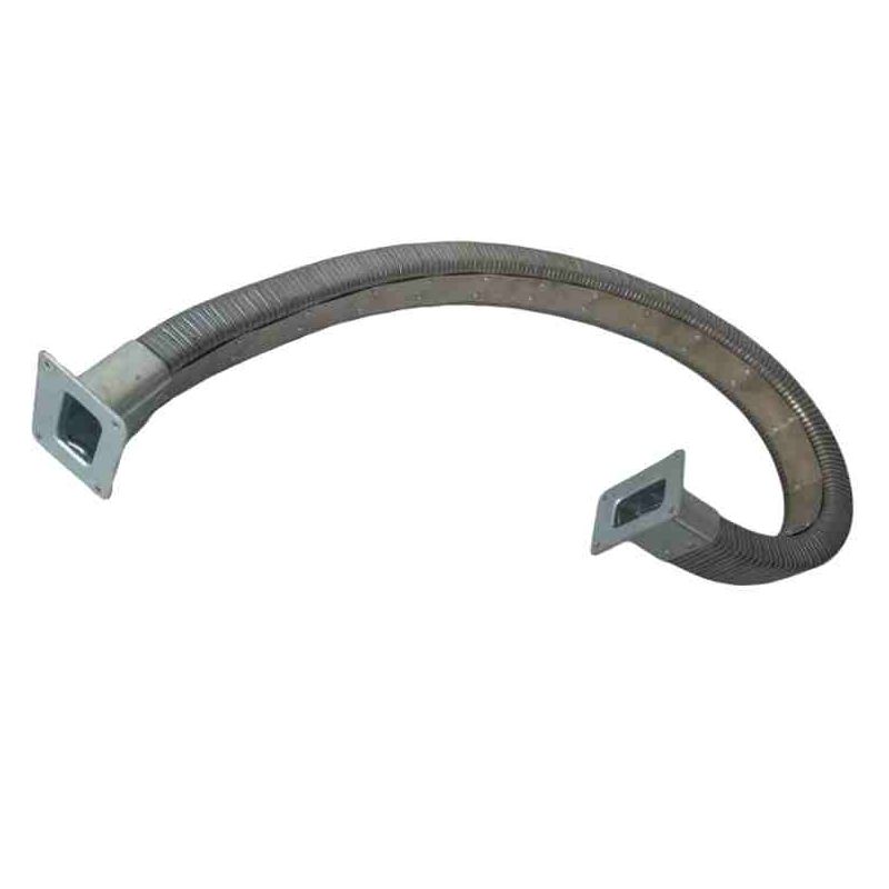
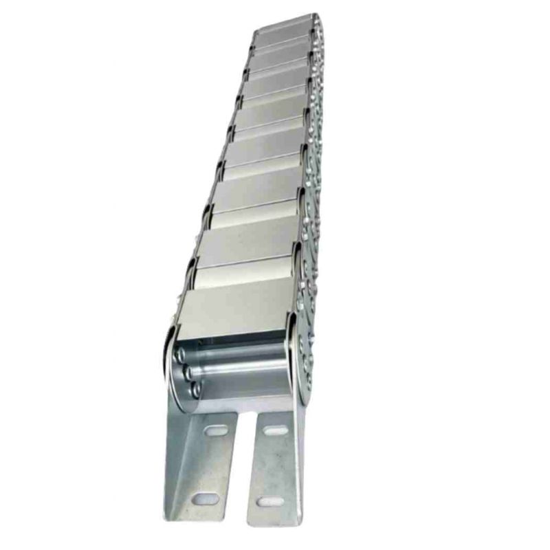
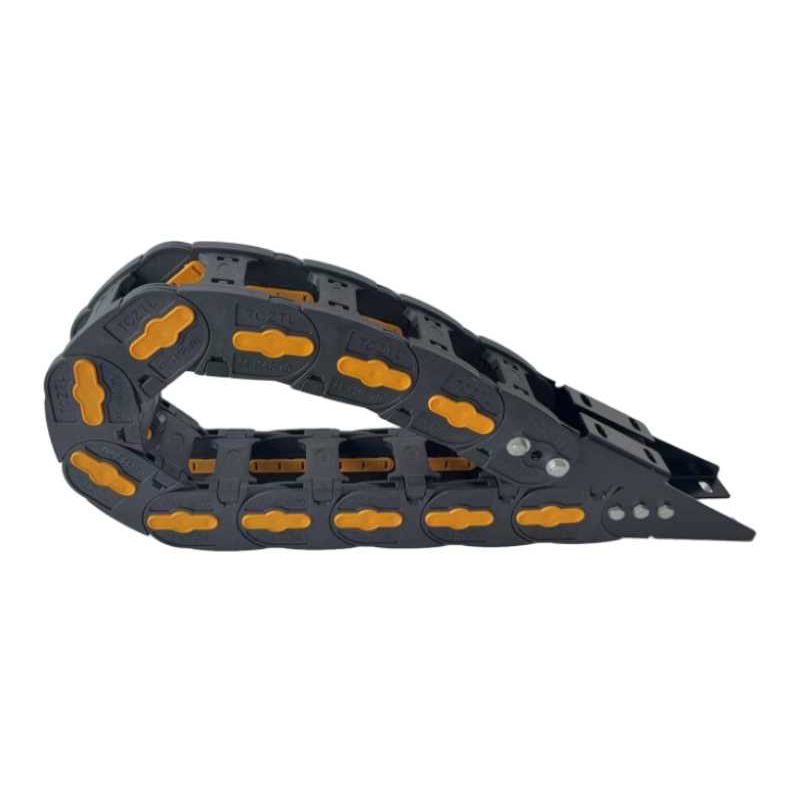
Modern high-speed industrial automation demands robust, wear-resistant, and high-load management solutions for flexible cables and heavy-duty hoses. Standard plastic carriers often fail under extreme physical impact, high temperatures, or corrosive environments. This premium bridge type steel drag chain is precision-engineered to bridge the gap between high-load capacity and delicate line management, serving as an advanced steel cable drag chain for global manufacturing environments.
To eliminate structural fatigue and premature rust—common issues in aggressive machinery setups—this heavy-duty metal drag chain offers an adaptable multi-material selection engineered for targeted industrial climates:
Zinc-Plated Steel (Cold/Hot-Dip Galvanized): Exceptional mechanical rigidity and foundational wear resistance for standard machine tool and indoor warehouse automation lines.
Colored Zinc Coating: Provides an extra layer of micro-oxidation resistance while adding a distinctive, premium industrial finish.
Dacromet Coating & Hot-Dip Galvanizing (Salt Spray Certified): Formulated specifically for harsh offshore, chemical processing, or outdoor operations. These surfaces undergo rigorous salt spray testing to verify long-term anti-corrosion survival without degradation.
Stainless Steel Structural Frame: The ultimate architectural choice for food-grade, pharmaceutical, or highly acidic processing environments where absolute zero-rust performance is non-negotiable.
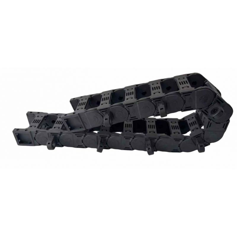
Unlike traditional solid enclosures that trap heat and collect debris, the structural bridge type steel drag chain framework utilizes lightweight, high-tensile aluminum alloy stays (crossbars). This unique design dramatically reduces the overall deadweight of the steel cable carrier while ensuring high structural stability during high-acceleration travel cycles.
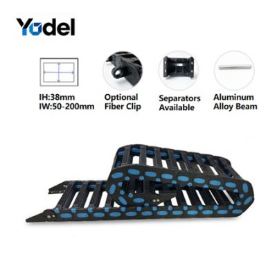
Every single opening is a dedicated component of this steel cable chain with stay holes. To counter the friction generated during continuous reciprocating motion, custom-molded nylon protective inserts (nylon rings) can be integrated directly inside each stay hole. These self-lubricating nylon grommets act as a low-friction barrier, completely isolating high-speed data cables and heavy duty cable networks from direct contact with the aluminum stay edges. This effectively prevents jacket wear, shielding your electrical signals from unexpected disruption or physical ruptures.
Application Environment: A heavy industrial manufacturing facility operating a high-speed CNC multi-axis plasma cutting gantry system in an environment filled with airborne metallic dust, heat spikes, and heavy hydraulic pressure lines.
The Challenge: The previous plastic tracks suffered from frequent structural cracking due to thermal radiation from the plasma torch, resulting in costly cable damage and operational downtime.
The Solution: The facility implemented our custom-engineered cnc drag chain constructed from high-strength stainless steel frames and aluminum alloy crossbars with integrated nylon rings.
The Outcome: The open bridge framework allowed metal dust to fall through effortlessly, avoiding internal accumulation. The self-lubricating nylon rings eliminated cable jacket abrasion despite continuous multi-axis travel. System uptime increased by 38%, and the operational lifespan of the internal control cables was extended threefold.
Selecting the exact physical dimensions of your steel cable drag chain is critical to ensuring smooth tracking and preventing mechanical binding. The inner clearance must accommodate the maximum outer diameter (OD) of your thickest cable bundle with adequate breathing room.
To determine the minimum required inner height (Hin) and inner width (Win) of the metal drag chain, utilize the following safety margin formulas:
Inner Width (Win) ≥ ∑d + (n × 0.10 × d)
Where dmax represents the largest cable outer diameter, ∑d is the cumulative sum of all cable/hose diameters, and n is the total number of lines inside the cross-section.
A restrictive bending radius causes internal copper fatigue in power lines. The bending radius (R) of your heavy-duty steel cable carrier should comply with the following rule:
For highly flexible pneumatic or dynamic control cables, a radius calculation of R ≥ 12 × dmax to15×dmax is recommended to optimize systemic operating life.
| Model | Inner Height mm | Inner Width mm | Outer Height mm | Outer Width mm | Bending Radius mm |
| TL65 | 25 | 25-300 | 44 | ±15 | 60 75 90 115 145 185 |
| TL75 | 30 | 30-300 | 50 | ±15 | 75 100 150 200 250 300 |
| TL80 | 35 | 30-300 | 55 | ±15 | 75 100 150 200 250 300 |
| TL95 | 50 | 50-350 | 70 | ±17 | 115 145 200 250 300 |
| TL100 | 55 | 50-350 | 75 | ±17 | 150 200 250 300 350 400 |
| TL115 | 60 | 60-400 | 86 | ±17 | 150 200 250 300 350 400 |
| TL125 | 70 | 70-450 | 100 | ±20 | 150 200 250 300 350 400 450 500 600 |
| TL155 | 90 | 90-450 | 130 | ±20 | 200 250 300 350 400 450 500-1000 |
| TL175 | 120 | 100-450 | 150 | ±30 | 200 250 300 350 400 450 500-1000 |
| TL180 | 115 | 100-1000 | 144 | ±30 | 200 250 300 350 400 450 500-1000 |
| TL225 | 170 | 100-1100 | 200 | ±30 | 300-1500 |
| TL250 | 180 | 100-1200 | 220 | ±35 | 300-1500 |
Yodel Technology Development Co., Ltd. is a professional cable carrier manufacturer in China with 15+ years of industry expertise, dedicated to providing various types, high-quality and cost-effective fastening solutions to global customers.[read more]


Contact Person : Tinny Tan
Te l : 8619922601285
E-mail : sales4@yodeldrag.com
Add : Chengnan Development Zone, Yanshan County, Hebei Province