sales4@yodeldrag.com
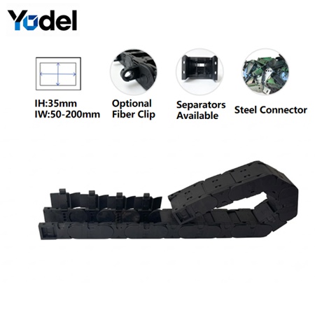
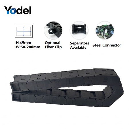
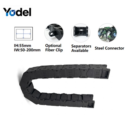
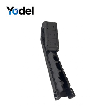
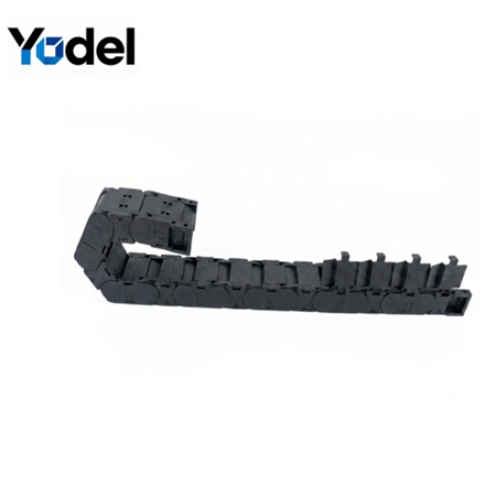
In hostile manufacturing environments, standard closed-type tracking loops pose a double-edged sword. While they shield against flying debris, conventional thin-walled designs succumb to structural buckling under the dense weight of enclosed cables. Over time, the horizontal crossbars warp, leading to joint oblonging, systematic sagging, and catastrophic line snaps.
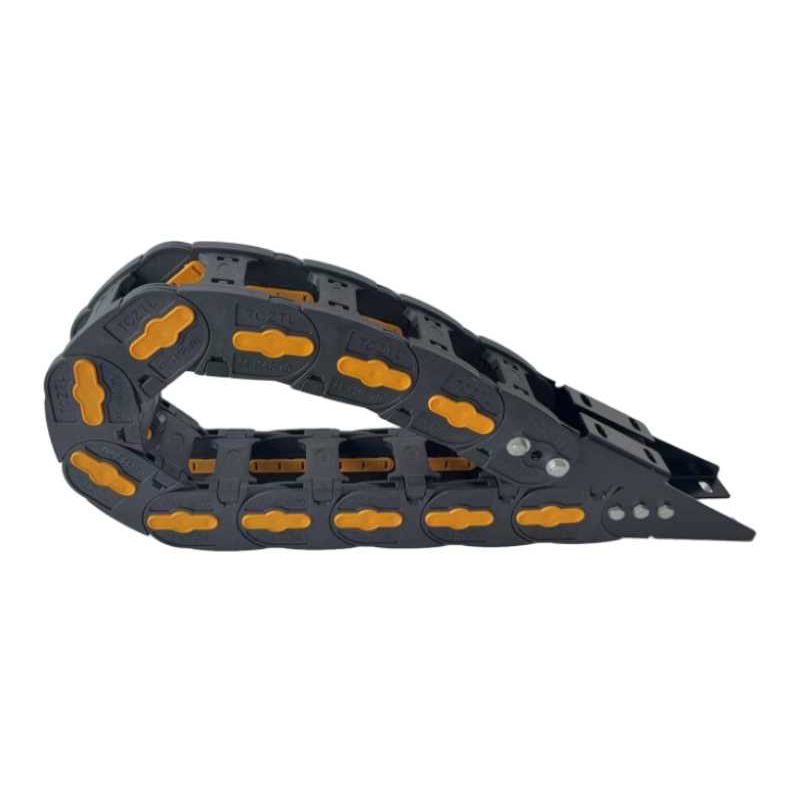
Our re-engineered heavy duty cable carrier series (engineered in standard 35mm, 45mm, and 55mm inner heights) shatters industry limitations by altering the fundamental geometry of dynamic protection. We didn't just increase the fiber content; we drastically beefed up the physical framework itself.
The Structural Dimension Upgrade: Where a common 35mm inner height track utilizes a flexible 12mm link side-wall, our high-fiber reinforced architectural variant boasts a massive 15mm thickness per individual link plate.
Combined with an entirely modified internal interlocking structure and molded from premium Nylon PA66 embedded with over 30% advanced high-fiber reinforcement, this nylon cable drag chain achieves unprecedented torsional stiffness. The thickened main body eliminates dynamic whipping during sudden directional reversals, guaranteeing an extended unsupported horizontal length (Lf) that functions flawlessly without requiring high-maintenance support trays or guide troughs.
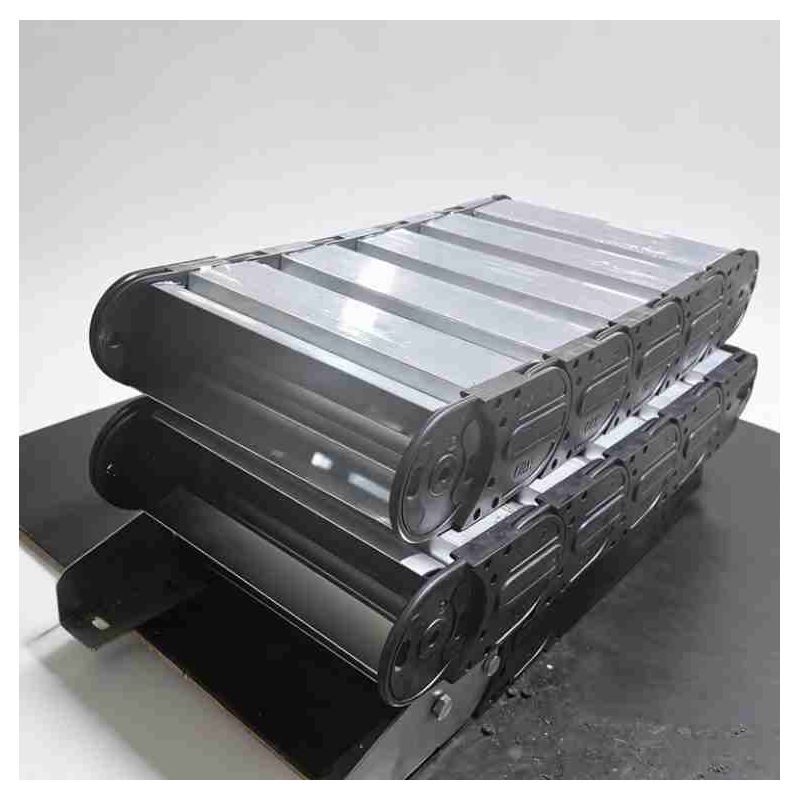
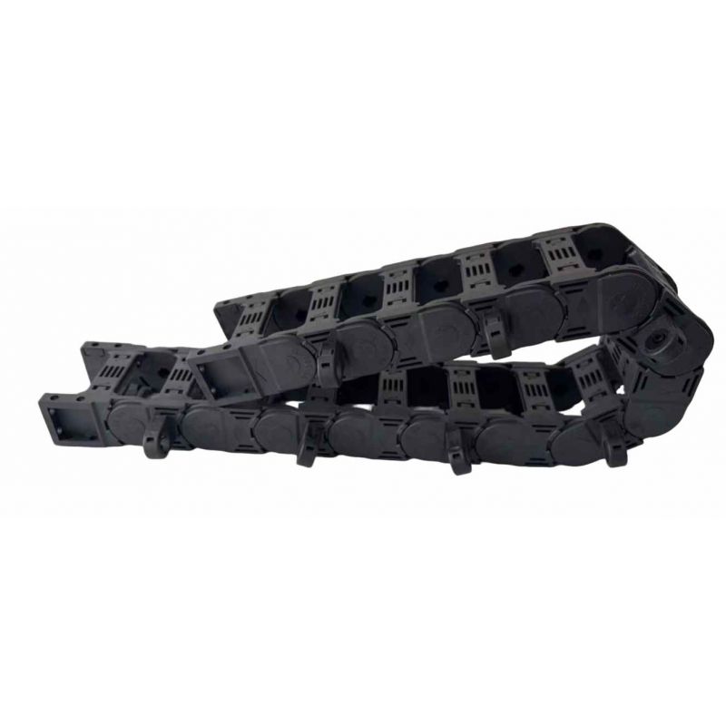
By fusing a 100% dust-tight, fully enclosed canopy with an aggressive, thick-walled frame and a rapid-access design, this plastic drag chain cable carrier series delivers peerless field endurance.
Massive Link Plates & Mainframe Wall Thickness: Localized structural scaling prevents horizontal sagging under excessive conduit payloads, providing ultimate dimensional stability.
100% Sealed Airborne Debris Shielding: The fully enclosed exterior shell acts as a complete protective barrier, completely blocking the ingress of hot metallic shavings, high-pressure coolant sprays, abrasive stone dust, or wood chips.
Rapid Side-Opening Latches: Enclosed carriers shouldn't complicate maintenance. The heavy-duty crossbars snap open effortlessly from the side. Field technicians can lay down dense lines or swap out pneumatic lines laterally within minutes—completely eliminating the need to disconnect complex terminal couplings or feed lines through a closed channel.
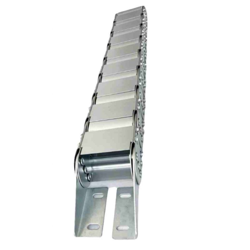
Heavy-Load Iron/Steel End Brackets: Standard plastic mounting tabs fracture under intense inertia. This series supports integrated heavy iron/steel end joints to handle rigid mechanical anchoring at the primary towing arm.
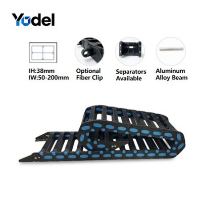
Strict Vertical Segregation Only: To maintain tracking balance and eliminate dynamic cable-on-cable friction, the interior chamber accommodates robust vertical separators. Note: This series features optimized vertical segregation only to maintain total link plate structural integrity under load.
Integrated Fiber-Optic Clips: Protect ultra-sensitive signal conduits. Special low-stress fiber-optic clips can be integrated into the internal web, keeping sensitive glass fiber data wires pinned safely along the neutral axis of the chain.
High-Flexing Ventilation Optimization: Despite its sealed outer shell, the interior architecture is optimized to work as a continuous cable hose carrier, dampening the kinetic heat buildup of heavy servo lines.
To fully comprehend the engineering impact of thickened link walls in a fully enclosed environment, let’s audit a real-world retrofitting project for an automated multi-axis industrial CNC milling and plasma-cutting gantry.
The Application Matrix: The system operated under high-frequency reciprocating acceleration cycles (>2.0G), managing a dense payload consisting of high-voltage spindle motor cables, shielded signal links, and a high-pressure gas hose. The combined internal weight neared 5.0 kg/m over an extended travel envelope.
The Failure Vector: The machinery originally ran a standard, thin-walled cnc cable drag chain. Because the links were only 12mm thick, the continuous heat from surrounding metal slag combined with the internal payload weight caused the track to bow laterally and sag midway. Hot metal fragments managed to melt through the thin cover, fusing the cables together and causing an unscheduled 12-hour factory shutdown.
Our Engineered Intervention: We deployed our upgraded TC35 Enclosed Thick-Walled Series ( 35mm inner height, featuring the massive 15mm link thickness and over 30% high-fiber PA66 matrix). We paired the carrier with heavy-duty steel end brackets to absorb the structural shocks, utilized internal vertical separators, and locked the sensor wires into our dedicated fiber-optic clips.
The Operational Result: The additional 3mm of reinforced wall thickness completely eliminated tracking deflection. The fully sealed outer canopy formed an impenetrable shield against flying plasma sparks and razor-sharp metal chips. Most importantly, when a hydraulic conduit required routine calibration months later, the maintenance crew utilized the side-opening drag chain latches to complete the swap in under 25 minutes—turning a historically catastrophic multi-hour gantry tear-down into a streamlined pit stop.
Avoid structural errors by utilizing our precise 3-step kinematic formula to configure your 35mm, 45mm, or 55mm thick-walled enclosed system:
Gather all cables and hoses intended for the cnc drag chain. Identify the absolute largest outer diameter (dmax).
The Safety Clearance Axiom: To account for dynamic centrifugal forces during high-speed travel, you must preserve a 10% to 15% clearance gap above your largest conduit.
Formula: Hi ≥dmax × 1.15
Largest conduit diameter≤30mm→Choose our 35mm Series (Massive 15mm Link Plate Thickness).
Largest conduit diameter≤mm→Choose our 45mm Series (Upgraded 18mm Link/Main Body Framework).
Largest conduit diameter≤48mm→ Choose our 55mm Series (Maximum Thickness Structural Profile).
Cables must never be stacked loosely or forced to twist over one another inside a fully enclosed environment.
Sum the outer diameters of all elements, add the 3mm material thickness of each vertical separator, and add a 10% lateral safety clearance.
Verify that this combined sum does not exceed the specified internal width (Bi) of the chosen plastic drag chain cable carrier.
Check your cable manufacturer's technical datasheet for the dynamic bending threshold (typically 10× to 12× the outer diameter).
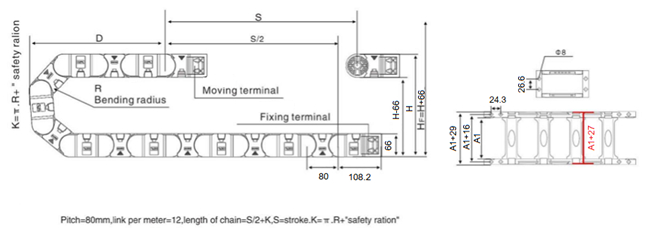
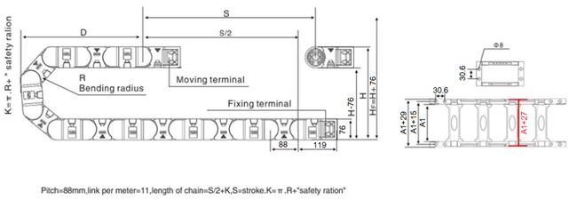
Select the bending radius (R) of the nylon cable drag chain that matches or exceeds this limit. A larger radius drastically reduces internal cable stress but requires a taller vertical clearance envelope (HF) within your machine housing layout.
Do not risk your critical automated infrastructure on thin-walled generic tracking lines. Whether you are outfitting a fleet of abrasive industrial cnc cable drag chain networks or searching for a 100% debris-proof cable hose carrier to stabilize heavy-duty pneumatic routing, our engineering division is ready to review your blueprints. Contact us today with your travel lengths, weights, and clearance parameters—we will provide a custom configuration within 24 hours.
| Model | Inner Height mm | Inner Width mm | Outer Height mm | Outer Width mm | Bending Radius mm |
| TC35.50 | 35 | 50 | 55 | 75 | 75 100 125 150 175 200 250 |
| TC35.75 | 35 | 75 | 55 | 100 | |
| TC35.100 | 35 | 100 | 55 | 125 | |
| TC35.125 | 35 | 125 | 55 | 150 | |
| TC35.150 | 35 | 150 | 55 | 175 | |
| TC35.175 | 35 | 175 | 55 | 200 | |
| TC35.200 | 35 | 200 | 55 | 225 |
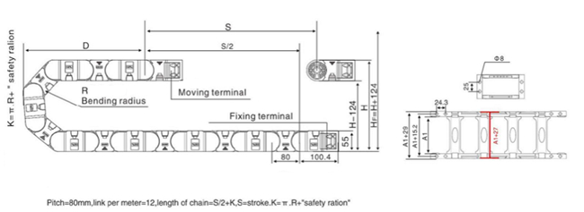
| Model | Inner Height mm | Inner Width mm | Outer Height mm | Outer Width mm | Bending Radius mm |
| TC45.50 | 45 | 50 | 65 | 77 | 75 100 125 150 175 200 250 |
| TC45.75 | 45 | 75 | 65 | 102 | |
| TC45.100 | 45 | 100 | 65 | 127 | |
| TC45.125 | 45 | 125 | 65 | 152 | |
| TC45.150 | 45 | 150 | 65 | 177 | |
| TC45.175 | 45 | 175 | 65 | 202 | |
| TC45.200 | 45 | 200 | 65 | 227 |
| Model | Inner Height mm | Inner Width mm | Outer Height mm | Outer Width mm | Bending Radius mm |
| TC55.50 | 55 | 50 | 75 | 80 | 100 125 150 200 250 300 |
| TC55.75 | 55 | 75 | 75 | 105 | |
| TC55.100 | 55 | 100 | 75 | 130 | |
| TC55.125 | 55 | 125 | 75 | 155 | |
| TC55.150 | 55 | 150 | 75 | 180 | |
| TC55.175 | 55 | 175 | 75 | 205 | |
| TC55.200 | 55 | 200 | 75 | 230 |
Yodel Technology Development Co., Ltd. is a professional cable carrier manufacturer in China with 15+ years of industry expertise, dedicated to providing various types, high-quality and cost-effective fastening solutions to global customers.[read more]


Contact Person : Tinny Tan
Te l : 8619922601285
E-mail : sales4@yodeldrag.com
Add : Chengnan Development Zone, Yanshan County, Hebei Province