sales4@yodeldrag.com
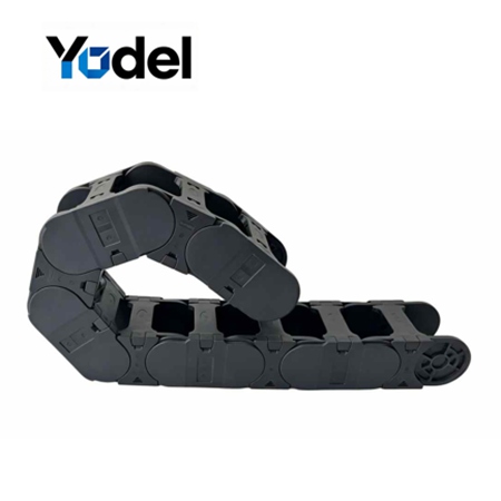
Standard nylon tracks fail on modern machinery not because of their length, but because their thin-walled links cannot withstand the constant torsional shock of directional reversals. When a generic track carries heavy conduits, the joints warp, causing the entire system to sag and snap.
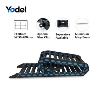
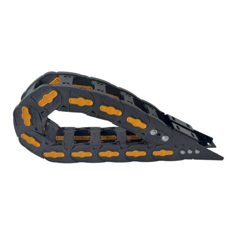
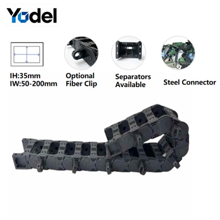
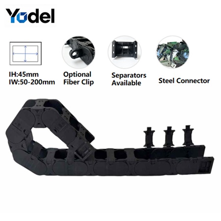
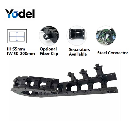
Our re-engineered heavy duty cable carrier series (35mm, 45mm, and 55mm inner heights) breaks away from standard industry molds. Molded from an advanced matrix of over 30% high-fiber reinforced Nylon PA66, this series completely shifts the geometric architecture of dynamic cable protection. We didn't just change the material; we beefed up the physical framework.Look at the physical difference: While a conventional 35mm inner height track utilizes a flimsy 12mm link side-wall, our high-fiber reinforced model boasts a massive 15mm thickness per individual link plate.
Every link, hinge-pin, and crossbar has been systematically thickened. This robust design delivers a colossal increase in unsupported structural reach (Lf), allowing the carrier to run further, faster, and under far greater payloads without requiring low-efficiency support trays.
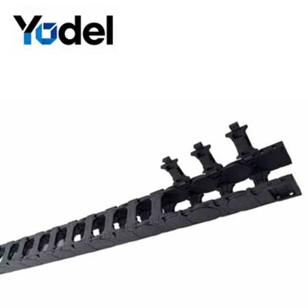
By combining an open-bridge design with an aggressive structural upgrade, this nylon cable drag chain delivers unmatched field longevity while keeping internal lines completely accessible.
Massive Link & Mainframe Wall Thickness: A localized increase in frame thickness prevents structural buckling during rapid acceleration spikes, turning it into the most stable plastic drag chain cable carrier on the market.
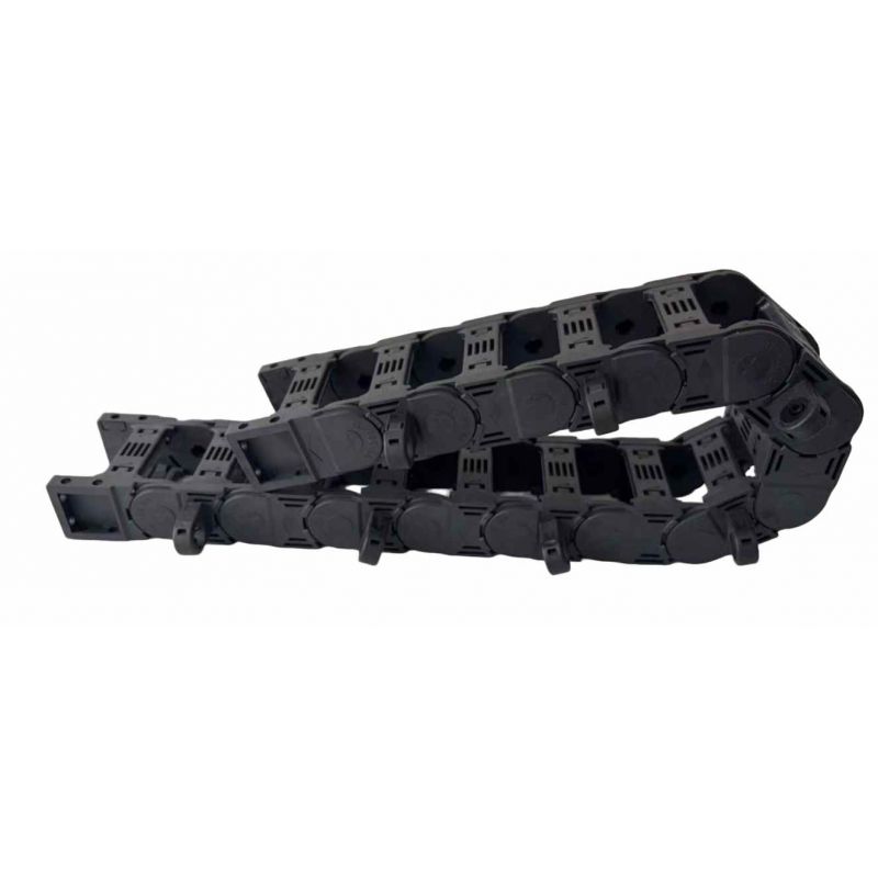
Rapid Side-Opening Latches: Maintenance shouldn't require a total machine shutdown. The crossbars unlatch smoothly from the side, allowing field engineers to lay down thick power cables or replace lines laterally without disconnecting any hydraulic or electrical terminals.
Heavy-Load Steel End Brackets: When high-inertia forces tug at your master driving point, standard plastic brackets can fracture. Our system offers heavy integrated steel end connectors to handle rigorous mechanical anchoring.
Strict Vertical Segregation: To maintain dynamic equilibrium, the internal chamber accommodates heavy-duty vertical separators. Note: This high-stress series features vertical segregation only to eliminate structural weak points caused by horizontal interlocking tabs.
Calibrated Fiber-Optic Clips: Safeguard sensitive lines. Custom fiber-optic clips can be locked directly onto the neutral bending web of the links, ensuring zero-pinch, low-tension paths for data-carrying glass fiber lines.
Open-Bridge Thermal Control: The open architecture of this cnc drag chain prevents heat retention, serving as a highly ventilated cable hose carrier that maximizes the lifespan of active pneumatic and high-voltage motor lines.
To understand the raw power of thicker walls, consider a real-world retrofitting project for a high-speed multi-axis industrial CNC router processing heavy wood and aluminum components.
The Application Context: The CNC gantry operated with an acceleration of 2.2G, hauling a dense bundle of servo power lines, shielded encoder data links, and a 25mm diameter high-pressure pneumatic hose. The total payload weight reached nearly 4.5 kg/m.
The Failure Vector: The factory had been utilizing standard, thin-walled cnc cable drag chain networks. Because the link plates were only 12mm thick, the continuous lateral friction caused the tracking joint pins to wear down and oblong. Within 3 months, the track began to sag midway, catching on the machine's mechanical frame and tearing out the internal encoder lines.
Our Engineered Intervention: We swapped out the failed track for our HDCC-35 Thick-Walled Series (35mm inner height, boasting the upgraded 15mm link thickness and a completely reinforced structural frame). We coupled the carrier with heavy-duty steel end brackets to absorb the 2.2G start-stop shocks, and utilized vertical separators to isolate the pneumatic hose from the signal lines.
The Result: The extra 3mm of high-fiber reinforced PA66 wall thickness completely counteracted the lateral bowing. The heavy duty cable carrier maintained a perfectly straight, crisp horizontal tracking profile over a 6-meter travel stroke. Furthermore, because of the side-opening drag chain geometry, the initial installation was completed in under an hour, and the factory has reported zero mechanical sagging or structural tracking wear for over 18 months of continuous operation.
Don't guess your automation layout. Use our mechanical formula to correctly choose between our 35mm, 45mm, and 55mm thick-walled models:
Find the single largest outer diameter (dmax) of the hoses or cables you intend to run inside the cnc drag chain.
The Clearance Axiom: You must maintain a 10% to 15% safety clearance above the thickest line to avoid dynamic crushing during high-radius bending.
Formula: Hi ≥ dmax ×1.15
Largest cable≤30mm→ Choose our 35mm Series (15mm Link Thickness).
Largest cable≤39mm→Choose our 45mm Series (Upgraded Link/Main Body Thickness).
Largest cable≤48mm→Choose our 55mm Series (Maximum Reinforcement Architecture).
Cables must never be stacked loosely on top of one another.
Sum the outer diameters of all cables/hoses, add the 3mm material thickness of each vertical separator, and add a 10% lateral safety gap.
Ensure this total is less than the internal width (Bi) of the plastic drag chain cable carrier.
Check your cable manufacturer's specification sheet for the dynamic bending threshold (usually 10×to12× the cable's outer diameter).
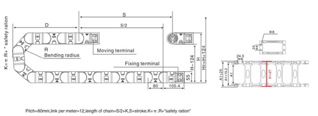
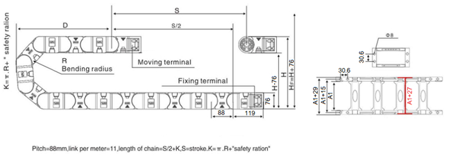
Select the bending radius (R) of the nylon cable drag chain that matches or exceeds this threshold. A larger radius increases internal cable lifespan but demands a taller vertical envelope space (HF) inside your machine layout.
| Model | Inner Height mm | Inner Width mm | Outer Height mm | Outer Width mm | Bending Radius mm |
| TS35.50 | 35 | 50 | 55 | 75 | 75 100 125 150 175 200 250 |
| TS35.60 | 35 | 60 | 55 | 85 | |
| TS35.75 | 35 | 75 | 55 | 100 | |
| TS35.100 | 35 | 100 | 55 | 125 | |
| TS35.125 | 35 | 125 | 55 | 150 | |
| TS35.150 | 35 | 150 | 55 | 175 | |
| TS35.175 | 35 | 175 | 55 | 200 | |
| TS35.200 | 35 | 200 | 55 | 225 |
| Model | Inner Height mm | Inner Width mm | Outer Height mm | Outer Width mm | Bending Radius mm |
| TS45.50 | 45 | 50 | 65 | 77 | 75 100 125 150 175 200 250 |
| TS45.60 | 45 | 60 | 65 | 87 | |
| TS45.75 | 45 | 75 | 65 | 102 | |
| TS45.100 | 45 | 100 | 65 | 127 | |
| TS45.125 | 45 | 125 | 65 | 152 | |
| TS45.150 | 45 | 150 | 65 | 177 | |
| TS45.175 | 45 | 175 | 65 | 202 | |
| TS45.200 | 45 | 200 | 65 | 227 |
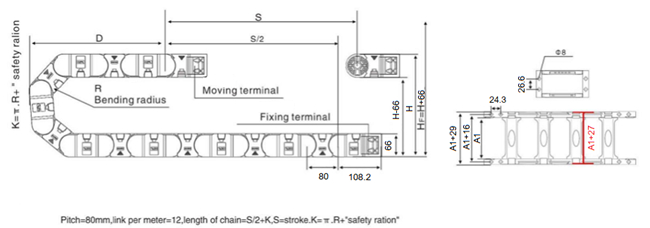
| Model | Inner Height mm | Inner Width mm | Outer Height mm | Outer Width mm | Bending Radius mm |
| TS55.50 | 55 | 50 | 75 | 80 | 100 125 150 200 250 300 |
| TS55.60 | 55 | 60 | 75 | 90 | |
| TS55.75 | 55 | 75 | 75 | 105 | |
| TS55.100 | 55 | 100 | 75 | 130 | |
| TS55.125 | 55 | 125 | 75 | 155 | |
| TS55.150 | 55 | 150 | 75 | 180 | |
| TS55.175 | 55 | 175 | 75 | 205 | |
| TS55.200 | 55 | 200 | 75 | 230 |
Yodel Technology Development Co., Ltd. is a professional cable carrier manufacturer in China with 15+ years of industry expertise, dedicated to providing various types, high-quality and cost-effective fastening solutions to global customers.[read more]


Contact Person : Tinny Tan
Te l : 8619922601285
E-mail : sales4@yodeldrag.com
Add : Chengnan Development Zone, Yanshan County, Hebei Province